AUTOMATIC RECTIFIERS FOR CATHODIC PROTECTION
MANUAL RECTIFIERS FOR CATHODIC PROTECTION
WITH VARIABLE VOLTAGE OUTPUT
SERIES RPC
From 10 to 120 Vcc, Of 10 Amp to 100 Amp
The Cathodic protection equipments of series RPC are specially designed to provide protection to the exposed metallic structures to a possible corrosion.
All metallic structure as pipelines, antenna, gas lines, aqueducts, bridges, wharves, communications towers, etc, are subject to the corrosive action of the environment that surround as air, sea water or the soil.
This condition is determined by the presence of corrosion currents through the metallic structure which behaves like an anode, taking place a material loss in the points where the current passes the structure to the means that surround it.
The best way to protect a structure is to modify it's electricalal potential in respect to the means that surround it, making it cathodic, in a way to eliminate this harmful current of corrosion.
The best way to carry out this is by means of a source of CC connected between the metallic structure and an electrode submerged in the means that surround this structure, injecting this way the necessary current until obtaining that the structure is left protected.
Since the corrosion currents vary in a variable measurement according to the conductivity of the environment that surround the structure, also the protection currents must be variable.
From this necessity ADI has developed a series of equipments of cathodic protection based on a rectifier of CC whose voltage of output is adjustable in a manual form by means of selective switches (one for big adjustments and another for the fine adjustments), in such way to be able to modify suitably the current injected in the structure to protect until it is protected.
The ADI cathodic protection equipments of series RPC is manufactured in standard form with monophase voltages of feeding of 220 V and triphasic of 3x 380 V, but to be able to obtain a greater flexibility in their use, due to the type of existing electrical systems in the places where these equipment are used, they are also manufactured with dual feeding of 380 / 1000 V, (two-phase), switchable by means of a metallic bridge, in such a way that the rectifier can be put in operation quickly.
Also they are available with two-phase feeding of 2,300 V.
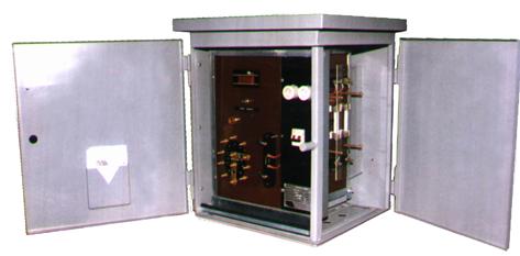
All the components of this equipment are mounted on a removable metallic frame, which rests within a metallic cabinet apt for enviromental inclemency, in this way in case of being necessary to remove the equipment to make only maintenance work, it will only be necessary to retire the frame.
The cabinet comes provided with a support to enable it to be mounted to a column by means of staples or simply hung.
The use of this technique allows to achive an equipment of excellent benefits and trustworthiness for use in heavy industry, and in places of difficult access.
TYPE OF USE
The rectifying equipment of series RPC, manually provides a voltage with adjustable output and its value will depend mainly on the value of the output current, that is the conductivity of the environment that surrounds the structure to protect.
Therefore its most frequent use is in zones where the conductivity of the environment that surround the structure has a moderate variation throughout the year, in such a way that the corrosion currents also stay relatively constant.
Therefore once fit the value of output voltage so that the structure is protected, the value of the potential is not modified substantially if the conductivity does not change too much.
GENERAL DESCRIPTION
The rectifying cathodic protection equipment of series RPC, basically are made up of a power transformer, triphase or monophase, whose secondary coils have multiple exits, which are exchanged by means of manualy selective switches, one for big adjustmentand and another one of fine adjustments.
The power transformer is of the dry type, class B, continuous service and has primary / secondary electrostatic screen in between.
The voltage selected in the secondary of the transformer, supplies a complete wave rectifyier, triphasic bridge or monophasic according to what corresponds, which uses mounted silicon diodes on aluminum dissipators.
The voltage of CC of output of the rectifying bridge is connected directly to the output terminal.
The equipment is supplied with a switch with fuses in its input and ultra fast fuses in the input of the rectifying bridge and varistores of metalic oxide against surges in the output of the rectifying bridge.
In parallel with each one of the diodes of the rectifying bridge is a protection network RC.
In order to make the measurements of voltages or the exhaust current, the rectifying equipment has a voltimeter - amperimeter, digital type, being able to select each one of the measurements by means of a switch.
Together with the instrument, the equipment is provided with a signal of operation by means of a pilot light that lights when the supply to the rectifier is connected to it.
In order to provide greater security in the operation of the rectifier all the elements of input (high voltage) are mounted directly on the side of the frame and the output elements (low voltage) are mounted on the front part of the frame, and therefore where the cabinet goes located in the frame, it has two doors, one at the side and anotherat the front, and is constructed in such a way that to open the side door it is necessary first to open the frontal door.
This way once put the equipment in service, the operator will have to open the frontal door to readjust the output voltage with no need to access to the supply terminals and therefor eliminating the chance of an accidental contact with these.
On the right side, on a phenolic resin plate, the input components will be located such as the terminals, the voltage disconnecting switch, the fuses, the on switch and the ground connection of the equipment
In the front and also on a phenolic resin plate, the elements of output such as the voltage switches will be located, voltimeter - amperimeter, the pilot light, the output switch, the fuses and the output terminal.
The connection of the cables are made by the inferior part of the cabinet, by means of a detachable metallic cover, in this cover the necessary holes for the passage of output - input cables will be able to be made.
The cabinet where the frame is mounted is apt for the inclemency, has waterproofed ceiling, two hinged doors, natural ventilation by means of screens in its inferior part and the underside edge of the ceiling, the finishing is with gray color epoxy painting.
The cabinet has a metallic support in its back part which allows its assembly by means of clips (U-bolts) to any type of column or post.
ACCESSORIES (OPTIONAL)
CURRENT INJECTION INDICATOR
Since these equipments generaly protect structures located in places of difficult access, like for example gasducts, pipe lines,energy towers, etc, ADI rectifying equipment series RPC, are available with a device to supervise the operation of the rectifier remotely by means of a beacon type light located in the outer part of the cabinet.
This device consists of a detector of the output current of the rectifier, if this is superior to a certain minimum value (normally from 1 to 2 Amp), an outer light will signal the condition which this self injecting current in the structure to protect.
This way the operator of the equipment will be able at once to determine if an equipment is in operation or not.
RUNNING HOURS COUNTER CLOCK
This device consists of an hour counter digital clock, supplied with a lithium battery (minimum duration 4 years), which is started when the rectifier is suppling current to the structure and stops when the rectifier quits working.
For this means, it has a detector of the output current of the rectifier, if it is superior to a certain minimum value (normally from 1 to 2 Amp), it enables the operation of the clock, otherwise it stops it.
This way the operator of the equipment will be able to by means of looking at the accumulated time in the clock if at some moment the equipment stopped its operation.