MANUAL RECTIFIERS FOR CATHODIC PROTECTION
AUTOMATIC
RECTIFIERS FOR CATHODIC PROTECTION
WITH STABILIZED OUTPUT
SERIES RPCC
From 30 To 100 Vcc, Of 10 Amp To 100 Amp
TO VOLTAGE, TO CURRENT OR CONSTANT POTENTIAL
The Cathodic Protection equipments of series RPCC
are specially designed to provide protection to the exposed metallic
structures to possible corrosion.
All metallic structure as
gas lines, pipeline, aqueducts,
bridges, wharves, antenna towers, etc, are subject to the corrosive
action of the elements that surrounds them as air, sea water or soil.
This condition is determined by the presence of
corrosion currents throughout the metallic structure which behaves like an anode,
producing a loss of material in points where the current passes by the structure to the
environment that surrounds it.
The best way to protect a structure is to vary its potential in regards to the elements that surround it making it cathodic, in this way we eliminate the flow of the damaging corrosion current.
The
practical way to carry this out, is by means of a source
of CC connected between the metallic structure and an electrode embedded in the
element that surrounds it, introducing in this way a current until we obtain a potential so that the
structure is left protected.
Due
to that corrosion currents vary in
accordance to the magnitude in conductivity of the elements that surround the structure,
the protecting currents will also be variable.
From this necessity, ADI
has developed a variety of cathode protection
equipments based on a rectifier of CC controlled
by thiristors in such a way that enable it to modify the electrical current introduced in the structure
in a totally automatic manner, protecting it according to the
variations in the corrosion current.
The
rectifying equipment continuously compares the
real value of the variable to control (output voltage, output tension or potential on the structure to protect), with
one adjustable desired value of this variable, modifying the output voltage of the
rectifying bridge until both values, real and the desired are balanced.
In
this manner, the operator for example, can adjust the output voltage of
the equipment in a value that allows this structure to remain protected in a totally automatic
way, the rectifier will
independently maintain that value of constant output voltage in variations of the
conductivity of the terrain or the
supply voltage and frequency of the
equipment.
ADI
rectifying equipment base their operation on the control phase of the thiristors that compose the rectifying bridge, for
which it is necessary to modify the conduction angle of those thiristors.
This is obtained by means of
digital control which have
three proportional controllers: one for the control of the output voltage,
a second controller for the total output current of the rectifier, and a third controller for the potential of the structure to protect.
The
output of any of these three controllers is applied in
cascade to one last controller of type proportional + integral
(P + I), whose value of output corresponds to the angle of conduction of
the thiristors.
This digital control
system is implemented by means of employing a microprocessor and associated digital
analogical circuits.
Divides the conduction angle of the thiristors in 11000
parts, assuring the stability in output voltage in + / - 1 %, considering variations
in load of 100 %
Limits the total output current to the structure,
maintaining the equipment within the safe zone of operation.
Selects different operation modes, whose characteristics are stored in
the memory of the control system
(EPROM).
Modifies the different values of adjustment of the rectifier (output voltage, maximum output current, desired potential, desired output current, etc) and the control system constants without the need to stop its operation, visualizing them in the front panel display.
Uses a digital display to enable it to make up to 10
measurements in sequential form such as output voltage, the output current,
structure potential, etc.
Accomplishes
the remote supervision of one or several equipments,
through a serial communications port type RS-232, that allows to
send by means of a modem through a communication system
(telephony, radio, satellite, etc), to a PC, the values of different measurements that
the equipment generates, the different states of operation and the status of alarms.
The use of this technique allows to conceive an equipment of
excellent benefits and high reliability for its use in heavy
industry, and in places of difficult access.
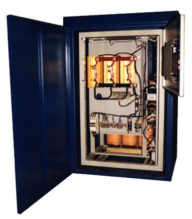
GENERAL DESCRIPTION
 The cathodic protection
rectifying equipment of series RPCC are
basically composed of a power
transformer whose output supplies a complete oscillation rectifying bridge with three
phase
or mono phase according to what corresponds.
The cathodic protection
rectifying equipment of series RPCC are
basically composed of a power
transformer whose output supplies a complete oscillation rectifying bridge with three
phase
or mono phase according to what corresponds.
When
exiting the rectifying bridge there is an inducer filter to reduce the ripple
effect of
the output voltage.
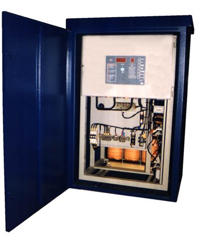
At the front of the equipment is a Control Panel in where are located the digital displays, which allow to make measurements of the different variables of the equipment, a set of buttons for rectifier operation and a group of LEDS that signal alarms and state of operation.
All the electronic components of the control system are
mounted in a curved-slide tray to allow an easy access to these components.
The
ADI Rectifying equipment series RPCC are manufactured in standard
form for mono phase input voltages of 220 V - 50 Hertz and three phase of 3 x 380 V - 50 Hertz
All the equipment
components are mounted on a metallic
frame, which fit within a metallic cabinet apt for inclemency, in this way, in case of being necessary to
remove the equipment to make maintenance, it is only necessary to remove this frame.
In
conformity with the type of structure to protect and the environment that surrounds the equipment, they have three ways of operation:
to Constant Voltage, to Constant Current or Constant Potential.
CONNECTION SCHEME OF AN AUTOMATIC CATHODIC PROTECTION EQUIPMENT
Constant
Voltage
Output
Its
most frequent use is in zones where the conductivity of
the surroundings of the structure remain relatively constant
throughout the year, in such a way that the corrosion currents also
stay relatively constant.
Therefore applying to a stabilized
voltage on the structure, it will remain protected as long as the conductivity does not
change too much.
Constant Electrical Output Rectifiers
Its
most frequent use is in zones where the structure to
protect is near other metallic structures with their corresponding protection rectifiers, interacting between
themselves.
This produces abrupt changes in the
corrosion currents due
to circulation of currents between structures with different degrees of protection.
Once the equipment
is installed and the required voltage output is set to protect the structure, the rectifier will maintain this
constant current
independent from variations in conductivity of surroundings or abrupt changes in
currents that circulate around
the structure to protect due to other near metallic structures.
Constant Potential Rectifiers
This model of rectifying equipment measures by means of a
sensor (for example an SO4Cu sensor), the structures potential in
regards to the soil and modifies the output voltage of the equipment until the value of the measured potential
is balanced with a value of required potential (previously adjusted).
TWO
WAY
OPERATION
REMOTE SUPERVISION
Due to that this equipments generally protect structures in hard to reach places, for example pipelines, power towers, etc. the ADI RPCC series rectifiers are provided with the possibility of a working status monitor using the serial connector type RS232 located on the control board.
Through this connection we can access data as voltage and current output, measured potentials, alarms, etc.
This information can be sent through a modem and transmission equipment to the receiving center for its processing.
Optionally the retrieval of information sent by each equipment can be done in a quick way from a vehicle as a truck or a small plane that recovers this information as it passes by the structures without having to go to each one individually.